Gambit: Viscous grid for a multi element airfoil, NHLP2D

In this tutorial we will learn how to generate a viscous unstructured grid for a multi element airfoil called  NHLP2D using Gambit.


Step 1. Importing

Open the Gambit GUI by typing gambit at the Linux prompt or clicking on the Gambit icon in Windows machine.

1. Change the default tolerance by going to  
Edit/Defaults/GEOMETRY/TOLERANCE. Change the EDGE_FACET value from 0.001 to 1.0e-08. This helps to build more precise geometry.
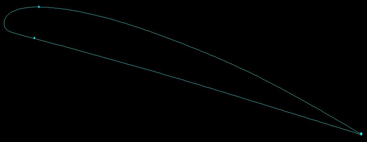
Fig 1, NHLP2D profile

2. Import the airfoil coordinates by going to File/Import/Vertex Data/ and pick the file nhlp2d.vertices file from the computer. The file should be a simple ascii file having 3 columns of x, y, z coordinates. Figure 1 shows the imported NHLP2D coordinates.
 Step 2. Creating the geometric domain:
Fig 2, Slat curve segmentation
1. Gambit is a single precision machine, so when we are having a boundary layer with first spacing as small as 1.0e-05 to 1.0e-07 m we end up having distorted cells in the boundary layer. So to avoid this, scale up the geometry by 1000 times.

2. Join the vertices by box picking or individually picking each vertices by using the NURB option. To do so, go to Geometry/EDGE COMMAND BUTTON/NURBS. It is advised to split each element into multiple parts as shown in  figures 2 tofor slat, main and flap respectively. Segmentation of each element helps in better control during edge meshing.

3. Create faces for slat, main and flap using the curves. Go to FACE/Create Face From Wireframe.

4. Create a circular surface with a radius of 3 chord by going to FACE COMMAND BUTTON/CREATE FACE, right click and choose Create Real Circular Face. In the Radius tab put 3,000 and press Apply. You will need to translate the newly created face in the x-direction to make sure that the multi element profile is sitting in the center. Next create a bigger circular Face of 100 chord radius by inputting a radius of 100,000. Remember that we have scaled the geometry by 1000 times, so the chord is not 1 but 1000. So you have totally 5 Faces, 3 belonging to the 3 elements of the multi element airfoil and 2 circular Faces.

Fig , Main element curve segmentation
  1. Fig , Flap curve segmentation
Fig , Trailing edge segmentation
5. Use boolean operation to get our final geometric domain. Go to BOOLEAN OPERATIONS, right click and choose Substract. In the first Face tab pick the big circular Face and in the second Substract Faces tab pick the inner smaller circular Face. Press Apply. A Face extending from the inner circle to outer circle is created and the inner circular Face is deleted out.  Next recreate the inner circular Face by going to FACE/Create Face From Wireframe and picking up the edge forming the inner circle. Once this is done use once again the BOOLEAN OPERATIONS to subtract each of the elements (slat, main, flap) Faces from the newly created inner circular Face. With this you have totally 2 Faces namely one inner circular Face with the 3 elements profile curved out and one outer circular Face extending from the inner circle to outer circular farfield.The geometry for generating the grid is ready.
    Fig 8, Inner domain
    Fig 9, Complete domain


     Step 3. Meshing the multi element airfoil Edges:

    1. Edge meshing will be done using the sizing function tool. Firstly change the default setting of sizing function by going to 
    Edit/Defaults/TOOLS/SFUNCTION. Change the default value of BGRID_MAX_TREE_DEPTH from 16 to 25 and that of BGRID_NONLINEAR_ERR_PERCENT from 25 to 15.

    2. The leading edge of slat and the trailing edge of the slat, main and flap elements will be meshed with 30 elements. Go to MESH COMMAND BUTTON/Mesh Edges, pick the leading and trailing edges of slat and the trailing edges of main and  flap elements and enter a Mesh count of 30. Press Apply. Mesh as shown in figure 11 is created. 
    1. Two sizing functions will be used to mesh the airfoil. One to capture the curvature of the airfoil and the other to put small cells at the trailing edge. Go to TOOL COMMAND BUTTON/Create Size Function.

    2. Sizing function 1: Choose Curvature in Type, for Sources and Attachment pick all the edges of the airfoil except the leading edge of the slat and the trailing edges of the slat, main and  flap.  Input the following parameters. Angle = 3, Growth rate = 1.125, Max. size = 13, Min. size = 0.01. Press Apply.

    3. Sizing function 2: Choose Fixed in Type. For Source pick the leading edge vertices of slat and  trailing edge vertices of slat, main and flap. For Attachment pick all the edges of the 3 elements excluding the leading edge of slat and trailing edge of slat, main and flap. Input the following parameters. Start size = 0.5, Growth rate = 1.125, Max. size = 13. Press Apply. This sizing function is applied to get a gradual mesh from the trailing edges.
    Fig 11, Trailing edge meshing
    1. Fig 10, Edge meshing for the multi element airfoil
    4. Now to mesh the airfoil go to MESH COMMAND BUTTON/Mesh Edges. Pick all the edges except the leading edge of slat and trailing edge of slat, main and flap. Press Apply. Edge mesh as shown in  figure 10 is generated.
    Step 4. Applying boundary layer padding:

    To resolve the boundary layer around the airfoil a viscous padding is created using the boundary layer template.
    Fig 12 , Boundary layer template
    1. Before creating the boundary layer template we will make a few changes in the default options. Go to Edit/Defaults/MESH/BLAYER/. Modify USE_FACETS_EVALS from 1 to 0 and QUICK_N_DIRTY from 1 to 0. This helps to get more accurate boundary layer.
    2. Go to MESH COMMAND BUTTON/BOUNDARY LAYER COMMAND BUTTON/Create Boundary Layer. Pick the option of Aspect ratio (last) under Algorithm. Make the following inputs for, First row (a) = 1.0e-02, Rows = 26, Last percent (c/w) = 50. We need a first spacing of 1.0e-05 meters  to resolve the boundary layer properly. Since we have already scaled the geometry by 1000 times, the input we will be making under First row (a) will be 1.0e-02. A white boundary layer template as seen in  figure 12 is created.


     Step 5. Creating the unstructured grid with boundary layer:

    Finally to generate the unstructured hybrid grid we will make use of two more sizing functions.


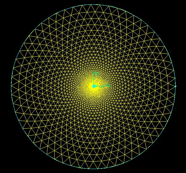
    Fig  13, Unstructured mesh for the whole domain
    Fig 14, Mesh around the NHLP2D airfoil
    Fig 15, Mesh in the cove region
    Fig 16, Mesh around the slat
    1. Go to TOOLS COMMAND BUTTON /SIZING-FUNCTION COMMAND BUTTON/Create Sizing Function

    2. Sizing function 3: Pick Meshed under Type, pick all the 3 edges of the airfoil as Source and  domain surface as Attachment. Let the Growth rate = 1.125 and Max.size20000.

    3. Sizing function 4: Let Type be Fixed. Pick the trailing edge vertex as Source and the domain surface as Attachment. Input the following parameters, Start size = 0.01, Growth rate = 1.125, Max. size = 20000

    4. Now to mesh the domain go to MESH COMMAND BUTTON/FACE COMMAND BUTTON/Mesh Faces. Pick the domain surface, let Elements  be Tri and Type be Pave. Press Apply. A hybrid grid as seen in figures 13-18 is generated.


      Fig 17, BL padding around slat leading edge
      Fig 18, BL padding around flap trailing edge


      Step 6. Quality check : 

       To check the quality of the cells in the grid pick the right bottom icon under Global Control called EXAMINE MESH.

      1. Pick Range under Display Type. Activate both quad and tria icons under 2D Element. Let the Quality Type be EquiSize Skew. Press Update. 

      2. The  color the cells in the grid changes with the skewness quality level. To check the worst cell, activate the button Show worst element. Under Transcript a message saying that the worst element quality value is 0.95. This needs to be corrected.
      Step 7. Applying boundary conditions  and exporting the mesh :

      1. As a last step before exporting the mesh we will apply boundary conditions. Go to ZONE COMMAND BUTTON/Specify Boundary Types.
       
      2. Pick the edges forming the slat and Name it as slat. Apply  Type as WALL. Similarly pick all the edges of main and  flap and give the Name as main and  flap respectively with Type as WALL.

      3. Pick the outer edge and Name it as farfield and  apply PRESSURE_FAR_FIELD under Type. Press Apply.

      4. Now go to CONTINUUM TYPE COMMAND BUTTON in ZONE. Here pick the two Faces representing the computational domain and  Name it as fluid with FLUID as Type.
      5. This completes applying boundary conditions. To export go to File/Export/Mesh/ and type out the name as nhlp2d.msh. Make sure to activate the button of Export 2-D(X-Y) Mesh.  If all the steps are done properly one will get the message "Mesh was successfully written to nhlp2d.msh" under Transcript.


      This completes the tutorial on viscous grid for NHLP2D airfoil using Gambit.


      Gambit: Viscous grid for naca0016 airfoil


      In this tutorial we will learn how to generate a viscous unstructured grid for a NACA0016 airfoil using Gambit.

      Open the Gambit GUI by clicking the Gambit icon in Windows or by typing gambit at the Linux prompt.

      Step 1. Importing

      1. Change the default tolerance by going to  Edit/Defaults/GEOMETRY/TOLERANCE. Change the EDGE_FACET value from 0.001 to 1.0e-08. This helps to build more accurate geometries.
      Fig 2, Curves using NURBS
      2. Import the airfoil coordinates by going to File/Import/Vertex Data/ and pickup the file naca0016.dat file from the computer.  The file should be a simple ascii file having 3 columns of xyz coordinates.

       Step 2. Creating the geometric domain:

      1. Gambit is a single precision grid generator, so when we are having a boundary layer with first spacing as small as 1.0e-05 to 1.0e-07 we end up having distorted cells in the boundary layer. To avoid this, scale up the geometry by 1000 times or in other words use a geometry which is in millimeters.
        
      Fig 3, Domain
      2. Join the points by box picking or individually picking each vertices by using the nurb option. Go to Geometry/EDGE COMMAND BUTTON/NURBS. It is advised to split the airfoil into 3 parts namely le, upper and lower and use 3 NURBS as shown in  figure 4. This helps to get smoother le curve than by capturing the airfoil profile by one curve.

      3. Create a surface out of the 3 curves representing the airfoil. Go to FACE/Create Face From Wireframe. Pick the 3 airfoil edges in Edges tab and press Apply.

      4. Create a circular surface with a radius of 20 chord by going to FACE COMMAND BUTTON/CREATE FACE, right click and choose Create Real Circular Face. In the Radius tab put 20,000 and press Apply

      Fig 4, Airfoil after boolean operation
      5. Use boolean operation to substract the airfoil surface from the bigger circular surface. Go to BOOLEAN OPERATIONS, right click and choose Substract. In the first Face tab pick the big circular surface and in the second Substract Faces tab pick the airfoil surface. Press Apply. One surface with the airfoil profile is created. The geometric domain is ready for meshing.
         
       Step 3. Meshing the airfoil edges:

      1. Edge meshing will be done using the sizing function tool. Firstly change the default setting of sizing function by going to  Edit/Defaults/TOOLS/SFUNCTION. Change the default value of BGRID_MAX_TREE_DEPTH from 16 to 25 and that of BGRID_NONLINEAR_ERR_PERCENT from 25 to 15. These parameters helps to get smoother point distributions.

      2. Two sizing functions will be used to mesh the airfoil. One to capture the curvature of the airfoil and the other to put finer points at the trailing edge. Go to TOOL COMMAND BUTTON/Create Size Function.

      3. Sizing function 1: Choose Curvature in Type, for Sources and Attachment pick all the edges of the airfoil.  Input the following parameters. Angle = 3, Growth rate = 1.125, Max. size = 13, Min. size = 0.01. Press Apply.

      4. Sizing function 2: Choose Fixed in Type. For Source pick the trailing edge vertex and for Attachment pick the edges of the airfoil. Input the following parameters. Start size = 0.5, Growth rate = 1.125, Max. size = 13. Press Apply.
      Fig 5, Edge meshing

      5. Now to mesh the airfoil go to MESH COMMAND BUTTON/Mesh Edges. Pick all the 3 airfoil edges and press Apply. Edge mesh as shown in  figure 5 is generated.
      Step 4. Applying boundary layer padding:
        
      1. To resolve the boundary layer around the airfoil a viscous padding is created using the boundary layer template.

      2.  Before creating the boundary layer template we will make a few changes in the default settings. Go to Edit/Defaults/MESH/BLAYER/. Modify USE_FACETS_EVALS from 1 to 0 and QUICK_N_DIRTY from 1 to 0. This helps to get more accurate boundary layer.


      3. Go to MESH COMMAND BUTTON/BOUNDARY LAYER COMMAND BUTTON/Create Boundary Layer. Pick the option of Aspect ratio (last) under Algorithm. Make the following inputs for, First row (a) = 1.0e-02, Rows = 26, Last percent (c/w) = 50. We need a first spacing of 1.0e-05 meters  to resolve the boundary layer properly. Since we have already scaled the geometry by 1000 times, the input we will be making under First row (a) will be 1.0e-02. 


      Fig 6,  Boundary layer template
      Note: First spacing is calculated based on the Reynolds number, reference length and estimated Y plus using standard Y plus calculator available on internet.

      4. To properly resolve the trailing edge, the option of Wedge corner shape is activated. Pick all the 3 edges forming the airfoil. Press Apply. A white boundary layer template as seen in  figure 6 is created.

      Step 5. Creating the unstructured grid with boundary layer:

      Finally to generate the unstructured hybrid grid we will make use of two more sizing functions.


      Fig 7, Mesh around airfoil
      Fig 8, Mesh for complete domain


      Go to TOOLS COMMAND BUTTON /SIZING-FUNCTION COMMAND BUTTON/Create Sizing Function

      1. Sizing function 3: Pick Meshed under Type, pick all the 3 edges of the airfoil as Source and  domain surface as Attachment. Let the Growth rate = 1.125 and Max.size =  20000.

      2. Sizing function 4: Let Type be Fixed. Pick the trailing edge vertex as Source and the domain surface as Attachment. Input the following parameters, Start size = 0.01, Growth rate = 1.125, Max. size = 20000. 

      3. Now to mesh the domain go to MESH COMMAND BUTTON/FACE COMMAND BUTTON/Mesh Faces. Pick the domain surface, let Elements  be Tri and Type be Pave. Press Apply. A hybrid grid as seen in figures 7, 8, 9 and 10 is generated.
      Fig 10, Mesh around trailing edge

      Fig 9, Mesh around leading edge
       Step 6. Quality check :

      To check the quality of the cells in the grid pick the right bottom icon under Global Control called EXAMINE MESH.
      Fig 11, Skewed cells at trailing edge
      Fig 12, Node movement
      Fig 13, Problem rectified
      1. Pick Range under Display Type. Activate both quad and tria icons under 2D Element. Let the Quality Type be EquiSize Skew. Press Update. 

      2. The  color the cells in the grid changes with the skewness quality level. To check the worst cell, activate the button Show worst element. Under Transcript a message saying that the worst element quality value is 0.95. This needs to be corrected.

      3. To make corrections, come out of Examine Mesh and go to Move Face Nodes under face meshing options. Here pick the domain face in Face and pick the node which is making the 2 cells skewed and physically move to the proper location. Make sure that the button of Smooth is active. This will rectify the problem.  
       Step 7. Applying boundary conditions  and            exporting the mesh :

      1. As a last step before exporting the mesh we will apply boundary conditions. Go to ZONE COMMAND BUTTON/Specify Boundary Types

      2. Pick the edges forming the airfoil and Name it as airfoil. Apply  Type as WALL.
      3. Pick the outer edge and Name it as farfield and  apply PRESSURE_FAR_FIELD under Type. Press Apply.
      4. Now go to CONTINUUM TYPE COMMAND BUTTON in ZONE. Here pick the domain surface, Name it as fluid and apply FLUID as Type.
      This completes applying boundary conditions. To export go to File/Export/Mesh/ and type out the name as naca0016.msh. Make sure to activate the button of Export 2-D(X-Y) Mesh.  If all the steps are done properly one will get the message "Mesh was successfully written to naca0016.msh" under Transcript.

      This completes the tutorial on viscous grid for Naca0016 airfoil using Gambit.